Temperature Controller Circuit Diagram A Basic Guide to Thermocouple Measurements Joseph Wu ABSTRACT Thermocouples are common temperature sensors used in a wide variety of commercial and industrial applications. While slightly less accurate than resistance temperature detectors (RTDs), thermocouples cover a wide temperature range, are self-powered, and have a fast response time. A thermocouple is a simple, robust and cost-effective temperature sensor used in a wide range of temperature measurement processes. Thermocouples are manufactured in a variety of styles, such as thermocouple probes, thermocouple probes with connectors, transition joint thermocouple probes, infrared thermocouples, bare wire thermocouple or even
Yes, a temperature sensor like a thermocouple is required to measure temperature with a multimeter. Unlike a standard temperature probe used for food or a traditional thermometer, the thermocouple is specifically designed to work with a multimeter to provide precise temperature readings for electrical components.

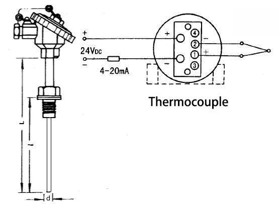
Two Ways to Measure Temperature Using Thermocouples Feature ... Circuit Diagram
measure temperature in many different ways that vary in cost of equipment and accuracy. Thermocouples are one of the most common sensors used to measure temperature because they are relatively inexpensive yet accurate sensors that can operate over a wide range of temperatures. View a 60-second video on how to take a Thermocouple Measurement To measure the temperature using a thermocouple, you cannot simply connect the thermocouple to a voltmeter or other measurement system, because the voltage measured is proportional to the temperature difference between the primary Sensor Measurement Systems white paper to learn about the different platforms for thermocouple measurements.

In order to make an absolute measurement, the thermocouple must be " referenced" to a known temperature on the other end of the sensor's cables. In the old days, this reference would be an ice bath of nearly frozen distilled water, which has a known temperature of 0°C (32° F). This circuit includes a high-precision ADC to measure the small-signal thermocouple voltage and a high-accuracy temperature sensor to measure the reference junction temperature. Both devices are controlled using an SPI interface from an external microcontroller. low-power analog front end—is used to measure the thermocouple voltage. The Infrared Sensors: Infrared thermometers measure surface temperature without contact, but thermocouples provide direct and more reliable readings in varying conditions. RTDs (Resistance Temperature Detectors) : RTDs offer excellent stability and accuracy for specific applications, but thermocouples are more cost-effective and versatile for

Temperature Measurement - KEYENCE America Circuit Diagram
The measurement instrument takes the generated voltage and converts it into a temperature reading by accounting for the reference junction, which is often done using a built-in junction sensor. The resulting voltage is then interpreted according to the type of thermocouple that is being used to measure temperature.
