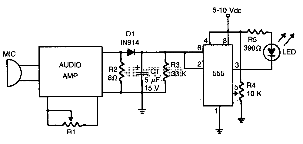
What is sound level meter Circuit Diagram To build a Sound Pressure Level Meter Circuit using IC CA3140 following are the steps to follow for assembling. Gather all the components as mentioned in the above circuit diagram. Connect pin 2 of IC1 CA3140 to one terminal of R5, and connect the other terminal of R5 to the positive of capacitor C3 and connect the negative of capacitor to GND.
Hello everyone, have come back to my channel. In today's video I will make audio level indicator with LM3915 ic. This is a very common simple circuit. There
How to make a sound level meter Circuit Diagram
This nifty sound level meter is a perfect one chip replacement for the standard analog meters. It is completely solid state and will never wear out. The whole circuit is based on the LM3915 audio level IC and uses only a few external components.
A simple sound level circuit made using LM3915 and few other basic components.Dreams Become Real by Kevin MacLeod is licensed under a Creative Commons Attrib

I make a Sound Level Indicator Using LED & Transistor Circuit Diagram
Sound Level Meter Circuit Diagram. If you are learning to be a communication engineer, playing with audio circuits is very important. This sound level meter is a simple hobby circuit to start with. You should build amplifier circuits and filter circuits to get a good grip on the subject. Learn how to build a simple sound level indicator circuit, similar to a VU meter, using basic electronic components! In this step-by-step tutorial, I'll guid This nifty sound level meter is a perfect one chip replacement for the standard analog meters. It is completely solid state and will never wear out. The whole circuit is based on the LM3915 audio level IC and uses only a few external components. Circuit diagram. Original Schematic. Parts C1 2.2uF 25V Electrolytic Capacitor R1 1K 1/4W Resistor
